
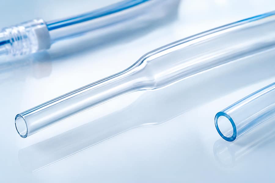
If you’ve spent time around catheter design, you’ve likely heard the term “bump tubing”—but the name doesn’t do much to explain what it actually is or why it matters. Bump tubing is a specialized extrusion where the tube’s diameter changes at a specific, controlled point along its length, rather than staying constant from end to end. That transition point—the “bump”—is precisely engineered rather than incidental, and it plays a functional role in many catheter and delivery system designs.
What Makes Bump Tubing Different
Standard extrusion produces tubing with a constant inner and outer diameter along its entire length. Bump tubing intentionally changes diameter—usually stepping from a smaller to a larger OD (or vice versa)—at one or more defined points, while maintaining tight tolerances on both diameters and a controlled, consistent transition zone between them.
This isn’t the same as simply bonding two different-diameter tubes together after the fact. True bump tubing is produced as a continuous extrusion, which means:
- No bond line or weak point at the transition
- Consistent wall integrity through the transition zone
- Tighter control over the transition length and taper angle
- No secondary assembly step required to create the diameter change
Why Diameter Transitions Matter in Catheter Design
A number of catheter and delivery system designs need a shaft that isn’t the same diameter everywhere:
Strain relief. A sudden change in stiffness or diameter—for example, where a shaft exits a handle or hub—can create a stress concentration point prone to kinking or fatigue failure. A gradual bump transition spreads that mechanical change over a controlled distance, reducing stress risers.
Nested or telescoping devices. In systems where one catheter or sheath rides over another, a bump transition can allow one section of the device to fit snugly over an inner component while a different section accommodates a different diameter requirement further along the shaft.
Hub and connector attachment. Many proximal ends need a larger diameter to accept a luer fitting, hub, or handle assembly, while the working length of the shaft needs to stay at a smaller profile for the anatomy it navigates.
Balloon or device attachment zones. Some balloon catheter designs use a diameter change to create a seating or bonding surface for a balloon or other component, improving bond strength and alignment during assembly.
Key Engineering Considerations
If you’re specifying bump tubing for a project, a few variables are worth discussing early with your extrusion partner:
- Transition length and taper angle. A more gradual transition reduces stress concentration but takes up more shaft length—a tradeoff against overall device length constraints.
- Wall thickness through the transition. Wall thickness needs to be controlled through the bump, not just at the two constant-diameter sections, to avoid a weak point.
- Tolerance stack-up. Both diameters, plus the transition itself, need independent tolerance control—this is a more demanding manufacturing target than a constant-diameter tube and should be scoped with your extrusion partner rather than assumed.
- Material behavior. Some materials transition more predictably than others under the heat and draw-down conditions bump tubing requires; this is worth validating with sample runs before committing to final tooling.
Is Bump Tubing Right for Your Design?
Bump tubing is worth considering any time your design has two functional requirements at different points along the shaft that call for different diameters—rather than defaulting to a constant-diameter tube with a bonded transition added afterward. The continuous extrusion approach typically offers better mechanical integrity and a cleaner path to regulatory and reliability testing, since there’s no secondary bond joint to characterize and validate.
Working on a design with a diameter transition requirement? Reach out to our engineering team to discuss feasibility and tolerances for your specific application.