
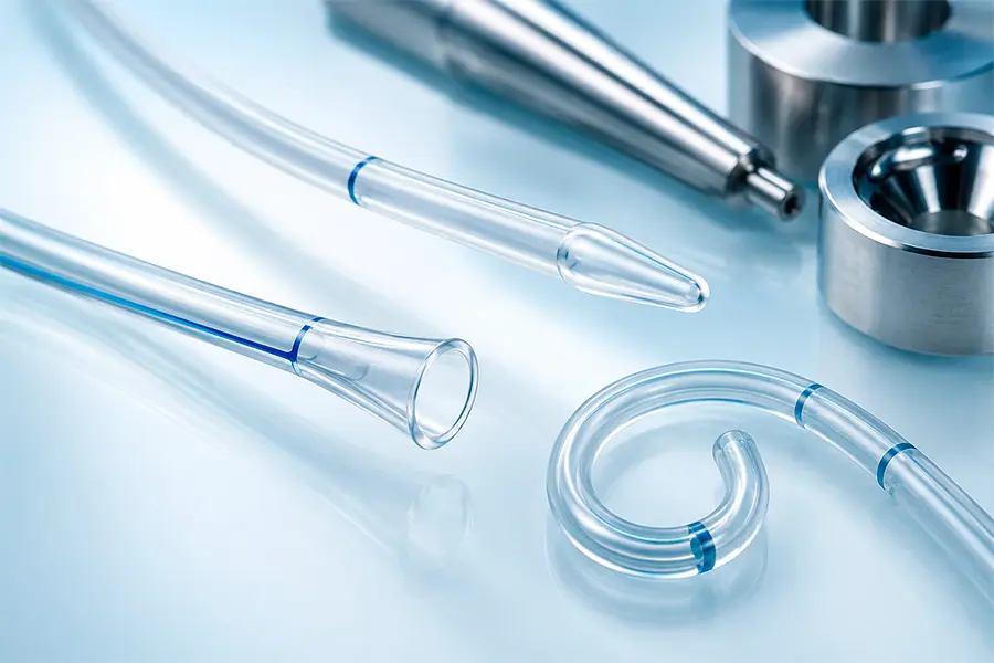
An extrusion line produces continuous straight tubing, but very few medical catheters go to market as a straight piece of plastic. To interact safely and effectively with human anatomy, catheter shafts undergo secondary thermal forming operations—such as tipping, flaring, expanding, or curve shaping.
Because polymers possess “thermal memory,” shaping them precisely requires a delicate balance of heat, dwell time, and cooling. For original equipment manufacturers (OEMs), understanding the tolerances achievable during thermal forming is vital for seamless downstream assembly and clinical efficacy.
Common Secondary Thermal Forming Operations
Before diving into tolerances, it helps to classify the primary ways thermal energy is used to reshape medical tubing:
- Distal Tipping: Tapering the end of the catheter into a blunt, bullet, or chamfered shape to ensure non-traumatic entry into blood vessels.
- Flaring and Expanding: Increasing the diameter of the tube at the proximal end to facilitate easier hub attachment, or expanding the distal end to create a receptive funnel for secondary devices.
- Curve Shaping (Molding): Baking the catheter shaft over a custom mandrel to impart a permanent, repeatable anatomical curve (e.g., Pigtail, Judkins Left/Right, or custom multi-axis curves).
Key Factors that Impact Thermal Forming Tolerances
Achieving tight dimensional tolerances during thermal forming depends on several material and process variables:
1. Material Durometer and Crystallinity
Softer polymers (e.g., 25D to 35D Pebax® or soft polyurethanes) flow easily under heat, making them highly receptive to tipping, but they are more susceptible to dimensional drift if the cooling cycle isn’t perfectly controlled. Harder polymers (e.g., 72D Pebax®, Nylon, PEEK) require much higher temperatures to reform and exhibit less post-mold shrinkage.
2. Wall Thickness Uniformity of the Base Extrusion
If the incoming single-lumen or multi-lumen extrusion has wall thickness variations (eccentricity), the thinner side will heat and melt faster than the thicker side. This leads to uneven material distribution, resulting in asymmetrical tips or weak flares.
3. Mold and Mandrel Precision
Thermal shaping relies on mating components—typically a heated geometric die and an internal support mandrel. The tolerance of the final part is directly constrained by the machining tolerances of these tooling components.
Standard vs. Precision Achievable Tolerances
While exact capabilities depend on the specific polymer blend and catheter profile, the following matrix outlines what OEMs can generally expect during secondary thermal forming:
| Thermal Operation | Standard Manufacturing Tolerance | High-Precision / Tight Tolerance |
| Tip Length | ±0.020” (±0.50 mm) | ±0.005” (±0.13 mm) |
| Flare / Expansion OD | ±0.003” (±0.08 mm) | ±0.001” (±0.025 mm) |
| Shaped Curve Angle | ±10° | ±3° to 5° |
| Concentricity (Tipped Ends) | 85% Minimum | 95% Minimum |
DFM Tips for OEM Sourcing and R&D Teams
- Avoid Over-Specifying Angle Tolerances: Due to the inherent elasticity of polymers, a molded curve will experience minor “spring-back” after it is removed from the fixture. Specifying a curve angle that is too tight (e.g., 1) drastically increases scrap rates and costs without providing clinical benefit.
- Account for Material Shrinkage: Always design proximal flares with the shrink-rate of the specific polymer matrix in mind, especially if the part undergoes subsequent sterilization (which can cause minor material relaxation).
Bring Precision to Your Secondary Operations
A high-quality extrusion can be ruined by poor secondary processing. At One Medical Extrusion, we utilize RF (Radio Frequency) heating technology and precision CNC-machined dies to deliver highly repeatable, tight-tolerance thermal forming. Contact our engineering team today to review your print specs.